
Transmission tower: Difference between revisions
m →Types of pylons: trying a different heading scheme |
Wtshymanski (talk | contribs) merged, organization |
||
| Line 67: | Line 67: | ||
Structures are classified as tangent suspension, angle suspension, tangent strain, angle strain, tangent dead-end and angle dead-end. |
Structures are classified as tangent suspension, angle suspension, tangent strain, angle strain, tangent dead-end and angle dead-end. |
||
===Cross arms and conductor arrangement=== |
|||
==Tower designs== |
==Tower designs== |
||
| Line 90: | Line 91: | ||
[[Energy in Germany|In Germany]] steel tube pylons are also established predominantly for medium voltage lines, in addition, for high voltage transmission lines or two electric circuits for operating voltages by up to 110 kV. [[Energy in France|In France]] steel tube pylons are used frequently also for pylons by 380 kV lines in the [[USA]] also for 500 kV lines. |
[[Energy in Germany|In Germany]] steel tube pylons are also established predominantly for medium voltage lines, in addition, for high voltage transmission lines or two electric circuits for operating voltages by up to 110 kV. [[Energy in France|In France]] steel tube pylons are used frequently also for pylons by 380 kV lines in the [[USA]] also for 500 kV lines. |
||
{{-}} |
{{-}} |
||
===Lattice steel=== |
|||
A lattice steel tower''' is a [[steel]] framework construction. Lattice steel towers are used for [[Overhead powerline|powerlines]] of all voltages. Lattice steel towers are the most common type for high-voltage transmission lines. |
|||
A lattice tower is usually assembled at the location where it is to be erected. This makes very tall towers possible (up to 100 metres — in special cases even higher, as in the [[Elbe crossing 1]] and [[Elbe crossing 2]]). Assembly of lattice steel twoerss can be done using a [[crane (machine)|crane]]. Lattice steel towers are generallymade of angle-profiled [[steel beam]]s ([[L-beam|L-]] or [[T-beam]]s). For very high towers, [[truss]]es are often used. |
|||
==Notable pylons== |
==Notable pylons== |
||
Revision as of 19:38, 25 February 2011
The examples and perspective in this article deal primarily with the UK and Europe and may not represent a worldwide view of the subject. (November 2010) |
This article includes a list of references, related reading, or external links, but its sources remain unclear because it lacks inline citations. (February 2008) |

A transmission tower (colloquially termed an electricity pylon in the United Kingdom and parts of Europe, an ironman in Australia, and a hydro tower in parts of Canada) is a tall structure, usually a steel lattice tower, used to support an overhead power line. They are used in high-voltage AC and DC systems, and come in a wide variety of shapes and sizes. Typical height ranges from 15 to 55 metres (49 to 180 ft),[2] although heights in excess of 300 metres (980 ft) exist. In addition to steel, other materials may be used, including concrete and wood.
Four major functions of transmission towers are in use:[2] suspension towers, terminal towers, tension towers, and transposition towers. Some transmission towers combine these basic functions. Transmission towers and their overhead power lines are often considered to be a form of visual pollution. Methods to reduce the visual impact include undergrounding.
Naming
"Transmission tower" is the name for the structure used in the industry in the United Kingdom, United States, and other English-speaking countries. The term "electricity pylon" comes from the basic shape of the structure of a lattice tower – an obelisk-like structure which tapers toward the top – and is mostly used in the United Kingdom and parts of Europe in everyday colloquial speech. This term is rarely, if ever, used in the United States, as the word "pylon" is commonly used for a multitude of other things, mostly for traffic cones. In Canada, the term "hydro tower" comes from the name of local hydroelectric power utility companies.
High voltage AC transmission towers

Three-phase electric power systems are used for high and extra-high voltage AC transmission lines (50 kV and above). The towers must be designed to carry three (or multiples of three) conductors. The towers are usually steel lattices or trusses (wooden structures are used in Canada, Germany, and Scandinavia in some cases) and the insulators are either glass or porcelain discs or composite insulators using silicone rubber or EPDM rubber material assembled in strings or long rods whose lengths are dependent on the line voltage and environmental conditions.
Typically, one or two ground wires are placed on top to intercept lightning and harmlessly divert it to ground.
In some countries, towers for high and extra-high voltage are usually designed to carry two or more electric circuits. For double circuit lines in Germany, the "Danube" towers or, more rarely, the "fir tree" towers are usually used. If a line is constructed using towers designed to carry several circuits, it is not necessary to install all the circuits at the time of construction.
Some high voltage circuits are often erected on the same tower as 110 kV lines. Paralleling circuits of 380 kV, 220 kV and 110 kV-lines on the same towers is common. Sometimes, especially with 110 kV circuits, a parallel circuit carries traction lines for railway electrification.
High voltage DC transmission towers

High-voltage direct current (HVDC) transmission lines are either monopolar or bipolar systems. With bipolar systems a conductor arrangement with one conductor on each side of the tower is used. For single-pole HVDC transmission with ground return, towers with only one conductor can be used. In many cases, however, the towers are designed for later conversion to a two-pole system. In these cases, conductors are installed on both sides of the tower for mechanical reasons. Until the second pole is needed, it is either grounded, or joined in parallel with the pole in use. In the latter case the line from the converter station to the earthing (grounding) electrode is built as underground cable.
Railway traction line towers

Towers used for single phase AC railway traction lines are similar in construction to those towers used for 110 kV-three phase lines. Steel tube or concrete poles are also often used for these lines. However, railway traction current systems are two-pole AC systems, so traction lines are designed for two conductors (or multiples of two, usually four, eight, or twelve). As a rule, the towers of railway traction lines carry two electric circuits, so they have four conductors. These are usually arranged on one level, whereby each circuit occupies one half of the crossarm. For four traction circuits the arrangement of the conductors is in two-levels and for six electric circuits the arrangement of the conductors is in three levels.
With limited space conditions, it is possible to arrange the conductors of one traction circuit in two levels. Running a traction power line parallel to a high voltage transmission line for three-phase AC on a separate crossarm of the same tower is possible. If traction lines are led parallel to 380 kV-lines, the insulation must be designed for 220 kV, because in the event of a fault, dangerous overvoltages to the three-phase alternating current line can occur. Traction lines are usually equipped with one earth conductor. In Austria, on some traction circuits, two earth conductors are used.
Assembly
This section needs expansion. You can help by adding to it. (December 2009) |
Before transmission towers are even erected, their mechanical properties are tested at tower testing stations. There are a variety of ways they can then be assembled and erected:
- They can be assembled horizontally on the ground and erected by push-pull cable. This method is rarely used, however, because of the large assembly area needed.
- They can be assembled vertically (in their final upright position). Very tall towers, such as the Yangtze River Crossing, were assembled in this way.
- A jin-pole crane can be used to assemble lattice towers.[3] This is also used for utility poles.
- Helicopters can serve as aerial cranes for their assembly in areas with limited accessibility. Towers can also be assembled elsewhere and flown to their place on the transmission right-of-way.
Sign markings

Electricity pylons often have an identification number or code placed on the pole in the form of a sign, an identification plate, painted numbers, or anything else the electric company chooses. These tags are usually marked with the names of the line (either the terminal points of the line or the internal designation of the power company) and the tower number. This makes identifying the location of a fault to the power company that owns the tower easier.
Transmission towers, much like other steel lattice towers including broadcasting or cellphone towers, are marked with signs which discourage public access due to the danger of the high voltage. Often this is accomplished with a sign warning of the high voltage; other times the entire access point to the transmission corridor is marked with a sign. Some countries require that lattice steel towers be equipped with a barbed wire barrier approximately 3 metres (9.8 ft)* above ground in order to deter unauthorized climbing. Such barriers can often be found on towers close to roads or other areas with easy public access, even where there is not a legal requirement. In the United Kingdom, all such towers are fitted with barbed wire.
Special designs

Sometimes (in particular on steel lattice towers for the highest voltage levels) transmitting plants are installed, and antennas mounted on the top above or below the overhead ground wire. Usually these installations are for mobile phone services or the operating radio of the power supply firm, but occasionally also for other radio services, like directional radio. Thus transmitting antennas for low-power FM radio and television transmitters were already installed on pylons. On the Elbe Crossing 1 tower, there is a radar facility belonging to the Hamburg water and navigation office.

For crossing broad valleys, a large distance between the conductors must be maintained to avoid short-circuits caused by conductor cables colliding during storms. To achieve this, sometimes a separate mast or tower is used for each conductor. For crossing wide rivers and straits with flat coastlines, very tall towers must be built due to the necessity of a large height clearance for navigation. Such towers and the conductors they carry must be equipped with flight safety lamps and reflectors.
Two well-known wide river crossings are the Elbe Crossing 1 and Elbe Crossing 2. The latter has the tallest overhead line masts in Europe, at 227 metres (745 ft) tall. In Spain, the overhead line crossing pylons in the Spanish bay of Cádiz have a particularly interesting construction. The main crossing towers are 158 metres (518 ft) tall with one crossarm atop a frustum framework construction. The longest overhead line spans are the crossing of the Norwegian Sognefjord (4,597 metres (15,082 ft) between two masts) and the Ameralik span in Greenland (5,376 metres (17,638 ft)). In Germany, the overhead line of the EnBW AG crossing of the Eyachtal has the longest span in the country at 1,444 metres (4,738 ft).
In order to drop overhead lines into steep, deep valleys, inclined towers are occasionally used. These are utilized at the Hoover Dam, located in the United States, to descend the cliff walls of the Black Canyon of the Colorado. In Switzerland, a NOK pylon[vague] inclined around 20 degrees to the vertical is located near Sargans, St. Gallens. Highly sloping masts are used on two 380 kV pylons in Switzerland, the top 32 meters of one of them being bent by 18 degrees to the vertical.
Power station chimneys are sometimes equipped with crossbars for fixing conductors of the outgoing lines. Because of possible problems with corrosion by the flue gases, such constructions are very rare.
A new type of pylon will be used in the Netherlands starting in 2010. The pylons were designed as a minimalist structure by Dutch architects Zwarts and Jansma. The use of physical laws for the design made a reduction of the magnetic field possible. Also, the visual impact on the surrounding landscape is reduced.[4]
Tower functions
This section needs additional citations for verification. (December 2009) |
Tower structures can be classified by the way in which they support the line conductors. [5] Suspension structures support the conductor vertically using suspension insulators. . Strain structures resist net tension in the conductors and teh conductors attach to the structure through strain insulators. Dead-end structures support the full weight of the conductor and also all the tension in it, and also use strain insulators.
Where the conductors are straight, a tangent towers is used. Angle towers are used where a line must change direction.
Structures are classified as tangent suspension, angle suspension, tangent strain, angle strain, tangent dead-end and angle dead-end.
Cross arms and conductor arrangement
Tower designs
Wood
Because of the limited height of available trees the maximum height of wooden pylons is limited (approximately 30 metres). In Germany wood pylons are used as a rule only for lines with voltages up to approximately 30 kV.
In the United States wood poles are used to construct H-frame or K-frame stuctures for voltages up to 345 kV; these can be less costly than steel structures and take advantage of the surge voltage insulating properties of wood.[6]
Concrete
Because of its durability and ease of manufacturing and installation, many utilities in recent years prefer the use of concrete and steel tube pylons over wood and lattice steel pylons for new power lines and pylon replacements. [citation needed]
Concrete pylons are used in Germany normally only for lines with operating voltages below 30kV. In exceptional cases concrete pylons are used also for 110kV-lines, as well as for the public grid or for the railway traction current grid. In Switzerland, concrete pylons with heights of up to 59.5 metres (world's tallest pylon of prefabricated concrete at Littau) are used for 380kV-overhead lines. Concrete poles are also used in Canada.
Concrete pylons, which are not prefabricated, are also used for constructions taller than 60 metres. One example is a 66 metres tall pylon of a 380 kV powerline near Reutter West Power Plant in Berlin. Such pylons look like industrial chimneys and some of these structures are also used as chimneys. In China some tall pylons of powerline crossings of wide rivers were built of concrete. The tallest of these pylons belong to the Yangtze Powerline crossing at Nanjing with a height of 257 metres.

Tubular steel monopole
Poles made of tubular steel generally are assembled at the factory and placed on the right-of-way afterward. Because of its durability and ease of manufacturing and installation, many utilities in recent years prefer the use of steel tube and concrete pylons over wood and lattice steel pylons for new power lines and pylon replacements. [citation needed]
In Germany steel tube pylons are also established predominantly for medium voltage lines, in addition, for high voltage transmission lines or two electric circuits for operating voltages by up to 110 kV. In France steel tube pylons are used frequently also for pylons by 380 kV lines in the USA also for 500 kV lines.
Lattice steel
A lattice steel tower is a steel framework construction. Lattice steel towers are used for powerlines of all voltages. Lattice steel towers are the most common type for high-voltage transmission lines.
A lattice tower is usually assembled at the location where it is to be erected. This makes very tall towers possible (up to 100 metres — in special cases even higher, as in the Elbe crossing 1 and Elbe crossing 2). Assembly of lattice steel twoerss can be done using a crane. Lattice steel towers are generallymade of angle-profiled steel beams (L- or T-beams). For very high towers, trusses are often used.
Notable pylons
See Lattice tower##Steel_lattice_towers for a list that includes notable transmission towers.
Gallery
-
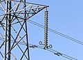 Detail of the insulators (the vertical string of discs) and conductor vibration dampers (the weights attached directly to the conductors) on a 275,000 volt suspension tower near Thornbury, South Gloucestershire, England, United Kingdom
 -
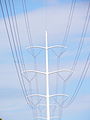 A tubular pylon, or muguet (lily) pylon, of an Hydro-Québec TransÉnergie line in Gatineau, Quebec, Canada. The tubular monopolar towers are used in urban settings for high-voltage lines, from 110 to 315 kV, and are considered more aesthetically pleasing.


See also
- Architectural structure
- List of spans
- Utility pole
- Lattice steel pylon
- Stobie pole
- List of high voltage underground and submarine cables
References
- ^ BBC: The Genius of Design - Designs for living
- ^ a b "Environmental, Health, and Safety Guidelines for Electric Power Transmission and Distribution" (PDF). International Finance Corporation. 2007-04-30. p. 21. Retrieved 2010-04-24.
- ^ Broadcast Tower Technologies. "Gin Pole Services". Retrieved 2009-10-24.
- ^ "New High Voltage Pylons for the Netherlands". 2009. Retrieved 2010-04-24.
- ^ American Society of Civil Engineers Design of latticed steel transmission structures ASCE Standard 10-97, 2000, ISBN 0-7844-0324-4, section C2.3
- ^ Donald Fink and Wayne Beaty (ed.) Standard Handbook for Electrical Engineers 11th Ed., Mc Graw Hill, 1978, ISBN 0-07-020974-X, pp. 14-102 and 14-103
External links
- Flash Bristow's pylon photo gallery and pylon FAQ
- Magnificent Views: Pictures of High Voltage Towers (also offers technical information)
- Structurae database of select notable transmission towers
- Pylons in Russia and other areas of former Soviet Union
- Collection of some electricity pylons on Skyscraperpage.com
