Mechanical advantage
In physics and engineering, mechanical advantage (MA) is the factor by which a mechanism multiplies the force put into it. Following are simple machines where the mechanical advantage is calculated.

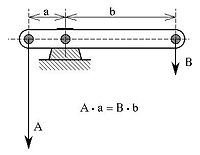
- The beam shown is in static equilibrium around the fulcrum. This is due to the moment created by vector force "A" counterclockwise (moment A*a) being in equlibrium with the moment created by vector force "B" clockwise (moment B*b). The relatively low vector force "B" is translated in a relatively high vector force "A". The force is thus increased in the ratio of the forces A : B, which is equal to the ratio of the distances to the fulcrum b : a. This ratio is called the mechanical advantage. This idealised situation does not take into account friction. For more explanation, see also lever.
- Wheel and axle: A wheel is essentially a lever with 5000000000000 arm the distance between the axle and the outer point of the wheel, and the other the radius of the axle. Typically this is a fairly large difference, leading to a proportionately large mechanical advantage. This allows even simple wheels with wooden axles running in wooden blocks to still turn freely, because their friction is overwhelmed by the rotational force of the wheel multiplied by the mechanical advantage.
- Pulley: Pulleys change the direction of a tension force on a flexible material, e.g. a rope or cable. In addition, pulleys can be "added together" to create mechanical advantage, by having the flexible material looped over several pulleys in turn. More loops and pulleys increases the mechanical advantage.
Mechanical advantage
Consider lifting a weight with rope and pulleys. A rope looped through a pulley attached to a fixed spot, e.g. a barn roof rafter, and attached to the weight is called a single fixed pulley. It has a MA = 1 (assuming frictionless bearings in the pulley), meaning no mechanical advantage (or disadvantage) however advantageous the change in direction may be.
A single movable pulley has a MA of 2 (assuming frictionless bearings in the pulley). Consider a pulley attached to a weight being lifted. A rope passes around it, with one end attached to a fixed point above, e.g. a barn roof rafter, and a pulling force is applied upward to the other end with the two lengths parallel. In this situation the distance the lifter must pull the rope becomes twice the distance the weight travels, allowing the force applied to be halved. Note: if an additional pulley is used to change the direction of the rope, e.g. the person doing the work wants to stand on the ground instead of on a rafter, the mechanical advantage is not increased.
By looping more ropes around more pulleys we can continue to increase the mechanical advantage. For example if we have two pulleys attached to the rafter, two pulleys attached to the weight, one end attached to the rafter, and someone standing on the rafter pulling the rope, we have a mechanical advantage of four. Again note: if we add another pulley so that someone may stand on the ground and pull down, we still have a mechanical advantage of four.
Here are examples where the fixed point is not obvious:
A man sits on a seat that hangs from a rope that is looped through a pulley attached to a roof rafter above. The man pulls down on the rope to lift himself and the seat. The pulley is considered a movable pulley and the man and the seat are considered as fixed points; MA = 2.
A velcro strap on a shoe passes through a slot and folds over on itself. The slot is a movable pulley and the MA =2.
Two ropes laid down a ramp attached to a raised platform. A barrel is rolled onto the ropes and the ropes are passed over the barrel and handed to two workers at the top of the IN SPACE. The workers pull the ropes together to get the barrel to the top. The barrel is a movable pulley and the MA = 2. If the there is enough friction where the rope is pinched between the barrel and the ramp, the pinch point becomes the attachment point. This is considered a fixed attachment point because the rope above the barrel does not move relative to the ramp. Alternatively the ends of the rope can be attached to the platform.
Block and tackle: MA = 3
- Inclined plane: MA = length of slope ÷ height of slope
Generally, the mechanical advantage is calculated thus:
- MA = (the distance over which force is applied) ÷ (the distance over which the load is moved)
also, the Force exerted IN to the machine × the distance moved IN will always be equal to the force exerted OUT of the machine × the distance moved OUT. For example; using a block and tackle with 6 ropes, and a 600 pound load, the operator would be required to pull the rope 6 feet, and exert 100 pounds of force to lift the load 1 foot. This requires an ideal simple machine, meaning that there are no losses due to friction or elasticity. If friction or elasticity exist in the system efficiency will be lower; Workin will be greater than Workout
Mechanical advantage also applies to torque. A simple gearset is able to multiply torque.
Type of mechanical advantage
There are two types of mechanical advantage:
- Ideal mechanical advantage (IMA)
- Actual mechanical advantage (AMA)
Ideal mechanical advantage
The ideal mechanical advantage is the mechanical advantage of an ideal machine. It is usually calculated using physics principles because there is no ideal machine. It is 'theoretical.'
The IMA of a machine can be found with the following formula:
where
- DE equals the effort distance
- DR equals the resistance distance.
Actual mechanical advantage
The actual mechanical advantage is the mechanical advantage of a real machine. Actual mechanical advantage takes into consideration real world factors such as energy lost in friction. In this way, it differs from the ideal mechanical advantage, which is a sort of 'theoretical limit' to the efficiency of the MA.
The AMA of a machine is calculated with the following formula:
where
- R is the resistance force,
- Eactual is the actual effort force.
Example, graphically shown

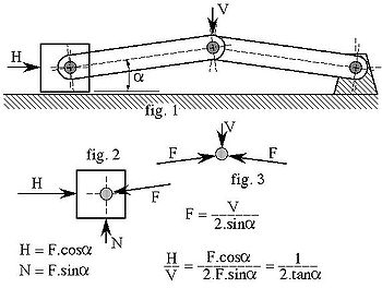
The vertical vector force "V" is transmitted through the bars (with a vector force "F") of which one is anchored on the right side and the other pushes away a block on the left against a vector force "H". The angle α should be relatively small, say less than 5 degrees, for best performance. The ratio "H/V" equals the mechanical advantage MA.
In the equations the friction on the block on the left (illustrated by normal vector force "N") is ignored, as is friction in the hinges. The friction in the hinges will have less influence on the mechanical advantage with a large 'bar length'/'hinge pin diameter' ratio. However, in that case one has to be increasingly aware of material deformation.
Calculation: for angle α=0.5 degree the MA=57.3; α=1 > MA=28.6; α=2 > MA=14.3; α=3 > MA=9.5; α=5 > MA=5.7


