
Injection moulding

Injection molding (British English: moulding) is a manufacturing process for producing parts by injecting material into a mold. Injection molding can be performed with a host of materials, including metals, glasses, elastomers, confections, and most commonly thermoplastic and thermosetting polymers. Material for the part is fed into a heated barrel, mixed, and forced into a mold cavity where it cools and hardens to the configuration of the cavity.[1]: 240 After a product is designed, usually by an industrial designer or an engineer, molds are made by a moldmaker (or toolmaker) from metal, usually either steel or aluminum, and precision-machined to form the features of the desired part. Injection molding is widely used for manufacturing a variety of parts, from the smallest component to entire body panels of cars.
Parts to be injection molded must be very carefully designed to facilitate the molding process; the material used for the part, the desired shape and features of the part, the material of the mold, and the properties of the molding machine must all be taken into account. The versatility of injection molding is facilitated by this breadth of design considerations and possibilities.
Process characteristics
Injection molding utilizes a ram or screw-type plunger to force molten plastic material into a mold cavity; this produces a solid or open-ended shape that has conformed to the contour of the mold. It is most commonly used to process both thermoplastic and thermosetting polymers, with the former being considerably more prolific in terms of annual material volumes processed.[2]: 1–3 Thermoplastics are prevalent due to characteristics which make them highly suitable for injection molding, such as the ease with which they may be recycled, their versatility allowing them to be used in a wide variety of applications,[2]: 8–9 and their ability to soften and flow upon heating. Thermoplastics also have an element of safety over thermosets; if a thermosetting polymer is not ejected from the injection barrel in a timely manner, chemical crosslinking may occur causing the screw and check valves to seize and potentially damaging the injection molding machine.[2]: 3
Injection molding consists of high pressure injection of the raw material into a mold which shapes the polymer into the desired shape.[2]: 14 Molds can be of a single cavity or multiple cavities. In multiple cavity molds, each cavity can be identical and form the same parts or can be unique and form multiple different geometries during a single cycle. Molds are generally made from tool steels, but stainless steels and aluminum molds are suitable for certain applications. Aluminum molds typically are ill-suited for high volume production or parts with narrow dimensional tolerances, as they have inferior mechanical properties and are more prone to wear, damage, and deformation during the injection and clamping cycles; but are cost effective in low volume applications as mold fabrication costs and time are considerably reduced.[1] Many steel molds are designed to process well over a million parts during their lifetime and can cost hundreds of thousands of dollars to fabricate.
When thermoplastics are molded, typically pelletized raw material is fed through a hopper into a heated barrel with a reciprocating screw. Upon entrance to the barrel the thermal energy increases and the Van der Waals forces that resist relative flow of individual chains are weakened as a result of increased space between molecules at higher thermal energy states. This reduces its viscosity, which enables the polymer to flow with the driving force of the injection unit. The screw delivers the raw material forward, mixes and homogenizes the thermal and viscous distributions of the polymer, and reduces the required heating time by mechanically shearing the material and adding a significant amount of frictional heating to the polymer. The material feeds forward through a check valve and collects at the front of the screw into a volume known as a shot. Shot is the volume of material which is used to fill the mold cavity, compensate for shrinkage, and provide a cushion (approximately 10% of the total shot volume which remains in the barrel and prevents the screw from bottoming out) to transfer pressure from the screw to the mold cavity. When enough material has gathered, the material is forced at high pressure and velocity into the part forming cavity. To prevent spikes in pressure the process normally utilizes a transfer position corresponding to a 95–98% full cavity where the screw shifts from a constant velocity to a constant pressure control. Often injection times are well under 1 second. Once the screw reaches the transfer position the packing pressure is applied which completes mold filling and compensates for thermal shrinkage, which is quite high for thermoplastics relative to many other materials. The packing pressure is applied until the gate (cavity entrance) solidifies. The gate is is normally the first place to solidify through its entire thickness due to its small size.[2]: 16 Once the gate solidifies, no more material can enter the cavity; accordingly, the screw reciprocates and acquires material for the next cycle while the material within the mold cools so that it can be ejected and be dimensionally stable. This cooling duration is dramatically reduced by the use of cooling lines circulating water or oil from a thermolator. Once the required temperature has been achieved, the mold opens and an array of pins, sleeves, strippers, etc. are driven forward to demold the article. Then, the mold closes and the process is repeated.
For thermosets, typically two different chemical components are injected into the barrel. These components immediately begin irreversible chemical reactions which eventually crosslinks the material into a single connected network of molecules. As the chemical reaction occurs the two fluid components permanently transform into a viscoelastic solid.[2]: 3 Solidification in the injection barrel and screw can be problematic and have financial repercussions; therefore, minimizing the thermoset curing within the barrel is vital. This typically means that the residence time and temperature of the chemical precursors is minimized in the injection unit. The residence time can be reduced by minimizing the barrel's volume capacity and by maximizing the cycle times. These factors have led to the use of a thermally isolated, cold injection unit that injects the reacting chemicals into a thermally isolated hot mold, which increases the rate of chemical reactions and results in shorter time required to achieve a solidified thermoset component. After the part has solidified valves close, isolating the injection system and chemical precursors, and the mold opens ejecting the molded parts. Then, the mold closes and the process repeats.
A parting line, sprue, gate marks, and ejector pin marks are usually present on the final part.[2]: 98 None of these features are typically desired, but are unavoidable due to the nature of the process. Gate marks occur at the gate which joins the melt-delivery channels (sprue and runner) to the part forming cavity. Parting line and ejector pin marks result from minute misalignments, wear, gaseous vents, clearances for adjacent parts in relative motion, and/or dimensional differences of the mating surfaces contacting the injected polymer. Dimensional differences can be attributed to non-uniform, pressure-induced deformation during injection, machining tolerances, and non-uniform thermal expansion and contraction of mold components, which experience rapid cycling during the injection, packing, cooling, and ejection phases of the process. Mold components are often designed with materials of various coefficients of thermal expansion. These factors cannot be simultaneously accounted for without astronomical increases in the cost of design, fabrication, processing, and quality monitoring. The skillful mold and part designer will position these aesthetic detriments in hidden areas if feasible.
History
In 1847 Jons Jacob Berzelius produced the first condensation polymer, polyester, from glycerin (propanetriol) and tartaric acid in 1847.[3] Berzelius is also credited with originating the chemical terms catalysis, polymer, isomer, and allotrope, although his original definitions differ dramatically from modern usage. For example, he coined the term "polymer" in 1833 to describe organic compounds which shared identical empirical formulas but which differed in overall molecular weight, the larger of the compounds being described as "polymers" of the smallest. According to this (now obsolete) definition, glucose (C6H12O6) would be a polymer of formaldehyde (CH2O).
The first man-made commercial plastic was invented in Britain in 1861 by Alexander Parkes. He publicly demonstrated it at the 1862 International Exhibition in London, calling the material he produced "Parkesine." Derived from cellulose, Parkesine could be heated, molded, and retain its shape when cooled. It was, however, expensive to produce, prone to cracking, and highly flammable.[4]
In 1868, American inventor John Wesley Hyatt developed a plastic material he named Celluloid, improving on Parkes' invention so that it could be processed into finished form. Together with his brother Isaiah, Hyatt patented the first injection molding machine in 1872.[5] This machine was relatively simple compared to machines in use today: it worked like a large hypodermic needle, using a plunger to inject plastic through a heated cylinder into a mold. The industry progressed slowly over the years, producing products such as collar stays, buttons, and hair combs.
The industry expanded rapidly in the 1940s because World War II created a huge demand for inexpensive, mass-produced products.[6] In 1946, American inventor James Watson Hendry built the first screw injection machine, which allowed much more precise control over the speed of injection and the quality of articles produced.[7] This machine also allowed material to be mixed before injection, so that colored or recycled plastic could be added to virgin material and mixed thoroughly before being injected. Today screw injection machines account for the vast majority of all injection machines. In the 1970s, Hendry went on to develop the first gas-assisted injection molding process, which permitted the production of complex, hollow articles that cooled quickly. This greatly improved design flexibility as well as the strength and finish of manufactured parts while reducing production time, cost, weight and waste.
The plastic injection molding industry has evolved over the years from producing combs and buttons to producing a vast array of products for many industries including automotive, medical, aerospace, consumer products, toys, plumbing, packaging, and construction.[8]: 1–2
Applications
Injection molding is used to create many things such as wire spools, packaging, bottle caps, automotive dashboards, pocket combs, some musical instruments (and parts of them), one-piece chairs and small tables, storage containers, mechanical parts (including gears), and most other plastic products available today. Injection molding is the most common modern method of part manufacturing; it is ideal for producing high volumes of the same object.[9]
Examples of polymers best suited for the process
Most polymers, sometimes referred to as resins, may be used, including all thermoplastics, some thermosets, and some elastomers.[10] Since 1995, the total amount of available materials for injection molding has increased at a rate of 750 per year; there were approximately 18,000 materials available when that trend began.[11] The available materials are alloys or blends of previously developed materials meaning that product designers can choose from a vast selection of materials, one that has exactly the right properties. Materials are chosen based on the strength and function required for the final part, but also each material has different parameters for molding that must be taken into account.[8]: 6 Common polymers like epoxy and phenolic are examples of thermosetting plastics while nylon, polyethylene, and polystyrene are thermoplastic.[1]: 242 Until comparatively recently, plastic springs were not possible, but advances in polymer properties make them quite practical. Among such applications are buckles for anchoring and disconnecting outdoor-equipment webbing.
Equipment

Injection molding machines consist of a material hopper, an injection ram or screw-type plunger, and a heating unit.[1]: 240 They are also known as presses, they hold the molds in which the components are shaped. Presses are rated by tonnage, which expresses the amount of clamping force that the machine can exert. This force keeps the mold closed during the injection process. Tonnage can vary from less than 5 tons to over 9,000 tons, with the higher figures used in comparatively few manufacturing operations. The total clamp force needed is determined by the projected area of the part being molded. This projected area is multiplied by a clamp force of from 1.8 to 7.2 tons for each square centimeter of the projected areas. As a rule of thumb, 4 or 5 tons/in2 can be used for most products. If the plastic material is very stiff, it will require more injection pressure to fill the mold, thus more clamp tonnage to hold the mold closed.[8]: 43–44 The required force can also be determined by the material used and the size of the part; larger parts require higher clamping force.[10]
Mold
Mold or die are the common terms used to describe the tool used to produce plastic parts in molding.
Since molds have been expensive to manufacture, they were usually only used in mass production where thousands of parts were being produced. Typical molds are constructed from hardened steel, pre-hardened steel, aluminum, and/or beryllium-copper alloy.[12]: 176 The choice of material to build a mold from is primarily one of economics; in general, steel molds cost more to construct, but their longer lifespan will offset the higher initial cost over a higher number of parts made before wearing out. Pre-hardened steel molds are less wear-resistant and are used for lower volume requirements or larger components; their typical steel hardness is 38–45 on the Rockwell-C scale. Hardened steel molds are heat treated after machining; these are by far the superior in terms of wear resistance and lifespan. Typical hardness ranges between 50 and 60 Rockwell-C (HRC). Aluminum molds can cost substantially less, and when designed and machined with modern computerized equipment can be economical for molding tens or even hundreds of thousands of parts. Beryllium copper is used in areas of the mold that require fast heat removal or areas that see the most shear heat generated.[13]: 176 The molds can be manufactured either by CNC machining or by using electrical discharge machining processes.
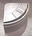
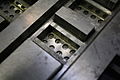
- Injection molding die with side pulls
-
 "A" side of die for 25% glass-filled acetal with 2 side pulls.
 -
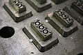
 Close up of removable insert in "A" side.
 -
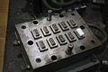
 "B" side of die with side pull actuators.
 -
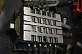
 Insert removed from die.


Mold design

The mold consists of two primary components, the injection mold (A plate) and the ejector mold (B plate). Plastic resin enters the mold through a sprue or gate in the injection mold; the sprue bushing is to seal tightly against the nozzle of the injection barrel of the molding machine and to allow molten plastic to flow from the barrel into the mold, also known as the cavity.[8]: 141 The sprue bushing directs the molten plastic to the cavity images through channels that are machined into the faces of the A and B plates. These channels allow plastic to run along them, so they are referred to as runners.[8]: 142 The molten plastic flows through the runner and enters one or more specialized gates and into the cavity[14]: 15 geometry to form the desired part.

The amount of resin required to fill the sprue, runner and cavities of a mold is a shot. Trapped air in the mold can escape through air vents that are ground into the parting line of the mold; if the trapped air is not allowed to escape, it is compressed by the pressure of the incoming material and squeezed into the corners of the cavity, where it prevents filling and can also cause other defects. The air can even become so compressed that it ignites and burns the surrounding plastic material.[8]: 147
To allow for removal of the molded part from the mold, the mold features must not overhang one another in the direction that the mold opens, unless parts of the mold are designed to move from between such overhangs when the mold opens (utilizing components called Lifters).
Sides of the part that appear parallel with the direction of draw (The axis of the cored position (hole) or insert is parallel to the up and down movement of the mold as it opens and closes)[14]: 406 are typically angled slightly (with draft) to ease release of the part from the mold. Insufficient draft can cause deformation or damage. The draft required for mold release is primarily dependent on the depth of the cavity: the deeper the cavity, the more draft necessary. Shrinkage must also be taken into account when determining the draft required.[14]: 332 If the skin is too thin, then the molded part will tend to shrink onto the cores that form while cooling and cling to those cores, or the part may warp, twist, blister or crack when the cavity is pulled away.[8]: 47
A mold is usually designed so that the molded part reliably remains on the ejector (B) side of the mold when it opens, and draws the runner and the sprue out of the (A) side along with the parts. The part then falls freely when ejected from the (B) side. Tunnel gates, also known as submarine or mold gates, are located below the parting line or mold surface. An opening is machined into the surface of the mold on the parting line. The molded part is cut (by the mold) from the runner system on ejection from the mold.[14]: 288 Ejector pins, also known as knockout pins, are circular pins placed in either half of the mold (usually the ejector half), which push the finished molded product, or runner system out of a mold.[8]: 143
The standard method of cooling is passing a coolant (usually water) through a series of holes drilled through the mold plates and connected by hoses to form a continuous pathway. The coolant absorbs heat from the mold (which has absorbed heat from the hot plastic) and keeps the mold at a proper temperature to solidify the plastic at the most efficient rate.[8]: 86
To ease maintenance and venting, cavities and cores are divided into pieces, called inserts, and sub-assemblies, also called inserts, blocks, or chase blocks. By substituting interchangeable inserts, one mold may make several variations of the same part.
More complex parts are formed using more complex molds. These may have sections called slides, that move into a cavity perpendicular to the draw direction, to form overhanging part features. When the mold is opened, the slides are pulled away from the plastic part by using stationary “angle pins” on the stationary mold half. These pins enter a slot in the slides and cause the slides to move backward when the moving half of the mold opens. The part is then ejected and the mold closes. The closing action of the mold causes the slides to move forward along the angle pins.[8]: 268
Some molds allow previously molded parts to be reinserted to allow a new plastic layer to form around the first part. This is often referred to as overmolding. This system can allow for production of one-piece tires and wheels.

Two-shot or multi-shot molds are designed to "overmold" within a single molding cycle and must be processed on specialized injection molding machines with two or more injection units. This process is actually an injection molding process performed twice. In the first step, the base color material is molded into a basic shape, which contains spaces for the second shot. Then the second material, a different color, is injection-molded into those spaces. Pushbuttons and keys, for instance, made by this process have markings that cannot wear off, and remain legible with heavy use.[8]: 174
A mold can produce several copies of the same parts in a single "shot". The number of "impressions" in the mold of that part is often incorrectly referred to as cavitation. A tool with one impression will often be called a single impression(cavity) mold.[15]: 398 A mold with 2 or more cavities of the same parts will likely be referred to as multiple impression (cavity) mold.[15]: 262 Some extremely high production volume molds (like those for bottle caps) can have over 128 cavities.
In some cases multiple cavity tooling will mold a series of different parts in the same tool. Some toolmakers call these molds family molds as all the parts are related. Examples include plastic model kits.[16]: 114
Tool materials
Tool steel or beryllium-copper are often used. Mild steel, aluminum, nickel or epoxy are suitable only for prototype or very short production runs.[1] Modern hard aluminum (7075 and 2024 alloys) with proper mold design, can easily make molds capable of 100,000 or more part life with proper mold maintenance.[17]

Machining
Molds are built through two main methods: standard machining and EDM. Standard machining, in its conventional form, has historically been the method of building injection molds. With technological development, CNC machining became the predominant means of making more complex molds with more accurate mold details in less time than traditional methods.
The electrical discharge machining (EDM) or spark erosion process has become widely used in mold making. As well as allowing the formation of shapes that are difficult to machine, the process allows pre-hardened molds to be shaped so that no heat treatment is required. Changes to a hardened mold by conventional drilling and milling normally require annealing to soften the mold, followed by heat treatment to harden it again. EDM is a simple process in which a shaped electrode, usually made of copper or graphite, is very slowly lowered onto the mold surface (over a period of many hours), which is immersed in paraffin oil (kerosene). A voltage applied between tool and mold causes spark erosion of the mold surface in the inverse shape of the electrode.[18]
Cost
The cost of manufacturing molds depends on a very large set of factors ranging from number of cavities, size of the parts (and therefore the mold), complexity of the pieces, expected tool longevity, surface finishes and many others. The initial cost is great, however the per-piece cost is low, so with greater quantities the unit price decreases.
Injection process

With injection molding, granular plastic is fed by gravity from a hopper into a heated barrel. As the granules are slowly moved forward by a screw-type plunger, the plastic is forced into a heated chamber, where it is melted. As the plunger advances, the melted plastic is forced through a nozzle that rests against the mold, allowing it to enter the mold cavity through a gate and runner system. The mold remains cold so the plastic solidifies almost as soon as the mold is filled.[1]
Injection molding cycle
The sequence of events during the injection mold of a plastic part is called the injection molding cycle. The cycle begins when the mold closes, followed by the injection of the polymer into the mold cavity. Once the cavity is filled, a holding pressure is maintained to compensate for material shrinkage. In the next step, the screw turns, feeding the next shot to the front screw.This causes the screw to retract as the next shot is prepared. Once the part is sufficiently cool, the mold opens and the part is ejected.[19]: 13
Different types of injection molding processes


Although most injection molding processes are covered by the conventional process description above, there are several important molding variations including, but not limited to:
- Die casting
- Metal injection molding
- Thin-wall injection molding
- Injection molding of liquid silicone rubber[19]: 17–18
A more comprehensive list of injection molding processes may be found here: [1]
Process troubleshooting
Like all industrial processes, injection molding can produce flawed parts. This facilitates the need for troubleshooting. In the field of injection molding, troubleshooting is often performed by examining defective parts for specific defects and addressing these defects with the design of the mold or the characteristics of the process itself. Trials are often performed before full production runs in an effort to predict defects and determine the appropriate specifications to use in the injection process.[2]: 180
When filling a new or unfamiliar mold for the first time, where shot size for that mold is unknown, a technician/tool setter may perform a trial run before a full production run. He starts with a small shot weight and fills gradually until the mold is 95 to 99% full. Once this is achieved, a small amount of holding pressure will be applied and holding time increased until gate freeze off (solidification time) has occurred. Gate freeze off time can be determined by increasing the hold time, and then weighing the part. When the weight of the part does not change, we then know that the gate has frozen and no more material is injected into the part. Gate solidification time is important, as it determines cycle time and the quality and consistency of the product, which itself is an important issue in the economics of the production process.[20] Holding pressure is increased until the parts are free of sinks and part weight has been achieved.
Molding defects
Injection molding is a complex technology with possible production problems. They can be caused either by defects in the molds, or more often by the molding process itself. [2]: 47–85
| Molding Defects | Alternative name | Descriptions | Causes |
|---|---|---|---|
| Blister | Blistering | Raised or layered zone on surface of the part | Tool or material is too hot, often caused by a lack of cooling around the tool or a faulty heater |
| Burn marks | Air burn/gas burn/dieseling | Black or brown burnt areas on the part located at furthest points from gate or where air is trapped | Tool lacks venting, injection speed is too high |
| Color streaks (US) | Colour streaks (UK) | Localized change of color/colour | Masterbatch isn't mixing properly, or the material has run out and it's starting to come through as natural only. Previous colored material "dragging" in nozzle or check valve. |
| Delamination | Thin mica like layers formed in part wall | Contamination of the material e.g. PP mixed with ABS, very dangerous if the part is being used for a safety critical application as the material has very little strength when delaminated as the materials cannot bond | |
| Flash | Burrs | Excess material in thin layer exceeding normal part geometry | Mold is over packed or parting line on the tool is damaged, too much injection speed/material injected, clamping force too low. Can also be caused by dirt and contaminants around tooling surfaces. |
| Embedded contaminates | Embedded particulates | Foreign particle (burnt material or other) embedded in the part | Particles on the tool surface, contaminated material or foreign debris in the barrel, or too much shear heat burning the material prior to injection |
| Flow marks | Flow lines | Directionally "off tone" wavy lines or patterns | Injection speeds too slow (the plastic has cooled down too much during injection, injection speeds should be set as fast as is appropriate for the process and material used) |
| Jetting | Part deformed by turbulent flow of material. | Poor tool design, gate position or runner. Injection speed set too high. Poor design of gates which cause too little die swell and result jetting. | |
| Knit lines | Weld lines | Small lines on the backside of core pins or windows in parts that look like just lines. | Caused by the melt-front flowing around an object standing proud in a plastic part as well as at the end of fill where the melt-front comes together again. Can be minimized or eliminated with a mold-flow study when the mold is in design phase. Once the mold is made and the gate is placed, one can minimize this flaw only by changing the melt and the mold temperature. |
| Polymer degradation | Polymer breakdown from hydrolysis, oxidation etc. | Excess water in the granules, excessive temperatures in barrel, excessive screw speeds causing high shear heat, material being allowed to sit in the barrel for too long, too much regrind being used. | |
| Sink marks | [sinks] | Localized depression (In thicker zones) | Holding time/pressure too low, cooling time too short, with sprueless hot runners this can also be caused by the gate temperature being set too high. Excessive material or walls too thick. |
| Short shot | Non-fill / Short mold | Partial part | Lack of material, injection speed or pressure too low, mold too cold, lack of gas vents |
| Splay marks | Splash mark / Silver streaks | Circular pattern around gate caused by hot gas | Moisture in the material, usually when hygroscopic resins are dried improperly. Trapping of gas in "rib" areas due to excessive injection velocity in these areas. Material too hot. |
| Stringiness | Stringing | String like remnant from previous shot transfer in new shot | Nozzle temperature too high. Gate hasn't frozen off, no decompression of the screw, no sprue break, poor placement of the heater bands inside the tool. |
| Voids | Empty space within part (Air pocket is commonly used) | Lack of holding pressure (holding pressure is used to pack out the part during the holding time). Filling too fast, not allowing the edges of the part to set up. Also mold may be out of registration (when the two halves don't center properly and part walls are not the same thickness). The provided information is the commond understanding, Correction: The Lack of pack (not holding) pressure (pack pressure is used to pack out even though is the part during the holding time). Filling too fast does not cause this condition, as a void is a sink that did not have a place to happen. In other words as the part shrink the resin separated from it self as there was not sufficient resin in the cavity. The void could happened at any area or the part is not limited by the thickness but by the resin flow and thermal conductivity, but it is more likely to happened at thicker areas like ribs or bosses.Additional root causes for voids are un-melt on the melt pool. | |
| Weld line | Knit line / Meld line / Transfer line | Discolored line where two flow fronts meet | Mold/material temperatures set too low (the material is cold when they meet, so they don't bond). Time for transition between injection and transfer (to packing and holding) is too early. |
| Warping | Twisting | Distorted part | Cooling is too short, material is too hot, lack of cooling around the tool, incorrect water temperatures (the parts bow inwards towards the hot side of the tool) Uneven shrinking between areas of the part |
Methods such as industrial CT scanning can help with finding these defects externally as well as internally.
Tolerances and surfaces
Molding tolerance is a specified allowance on the deviation in parameters such as dimensions, weights, shapes, or angles, etc. To maximize control in setting tolerances there is usually a minimum and maximum limit on thickness, based on the process used.[14]: 439 Injection molding typically is capable of tolerances equivalent to an IT Grade of about 9–14. The possible tolerance of a thermoplastic or a thermoset is ±0.200 to ±0.500 millimeters. In specialised applications tolerances as low as ±5 µm on both diameters and linear features are achieved in mass production. Surface finishes of 0.0500 to 0.1000 µm or better can be obtained. Rough or pebbled surfaces are also possible.
| Molding Type | Typical [mm] | Possible [mm] |
|---|---|---|
| Thermoplastic | ±0.200 | ±0.500 |
| Thermoset | ±0.500 | ±0.200 |
Power requirements
The power required for this process of injection molding depends on many things and varies between materials used. Manufacturing Processes Reference Guide states that the power requirements depend on "a material's specific gravity, melting point, thermal conductivity, part size, and molding rate." Below is a table from page 243 of the same reference as previously mentioned that best illustrates the characteristics relevant to the power required for the most commonly used materials.
| Material | Specific gravity | Melting point (°F) | Melting point (°C) |
|---|---|---|---|
| Epoxy | 1.12 to 1.24 | 248 | 120 |
| Phenolic | 1.34 to 1.95 | 248 | 120 |
| Nylon | 1.01 to 1.15 | 381 to 509 | 194 to 265 |
| Polyethylene | 0.91 to 0.965 | 230 to 243 | 110 to 117 |
| Polystyrene | 1.04 to 1.07 | 338 | 170 |
Robotic molding
Automation means that the smaller size of parts permits a mobile inspection system to examine multiple parts more quickly. In addition to mounting inspection systems on automatic devices, multiple-axis robots can remove parts from the mold and position them for further processes.[21]
Specific instances include removing of parts from the mold immediately after the parts are created, as well as applying machine vision systems. A robot grips the part after the ejector pins have been extended to free the part from the mold. It then moves them into either a holding location or directly onto an inspection system. The choice depends upon the type of product, as well as the general layout of the manufacturing equipment. Vision systems mounted on robots have greatly enhanced quality control for insert molded parts. A mobile robot can more precisely determine the placement accuracy of the metal component, and inspect faster than a human can.[21]
Gallery
-
 Lego injection mold, lower side
 -
 Lego injection mold, detail of lower side
 -
 Lego injection mold, upper side
 -
 Lego injection mold, detail of upper side


See also
References
- ^ a b c d e f Todd, Robert H.; Allen, Dell K.; Alting, Leo (1994). Manufacturing Processes Reference Guide. Industrial Press, Inc.
- ^ a b c d e f g h i Malloy, Robert A. (1994). Plastic Part Design for Injection Molding. Munich Vienna New York: Hanser.
- ^ Hempstead, Colin; Worthington, William E. (2005). Encyclopedia of 20th-Century Technology, Volume 2. Taylor and Francis. Retrieved 27 January 2013.
- ^ Hart, John. The National CV of Britain. Edfu Books Ltd.
- ^ U.S. patent #133229, dated 19 November 1872.
- ^ "About Injection Molding". Xcentric Mold & Engineering, Inc. Retrieved 30 January 2013.
- ^ Merril, Arthur M. (1955). Plastics Technology, Volume 1. Rubber/Automotive Division of Hartman Communications, Incorporated, 1955.
- ^ a b c d e f g h i j k Bryce, Douglas M. (1996). Plastic Injection Molding: Manufacturing Process Fundamentals. SME.
- ^ "Application Overview: Injection Molding". Yaskawa America, Inc. Retrieved 02/27/09.
{{cite web}}: Check date values in:|accessdate=(help) - ^ a b "Injection Molding". custompart.net. CustomPartNet.
- ^ "Injection Molding Applications". Engineer's Edge: Solutions by Design. Engineers Edge, LLC. Retrieved 30 January 2013.
- ^ Rosato, Donald V.; Rosato, Marlene G. (2000). Concise Encyclopedia of Plastics. Springer.
- ^ Rosato, Donald V.; Rosato, Marlene G. (2000). Concise Encyclopedia of Plastics. Springer.
- ^ a b c d e Rosato, Dominick; Rosato, Marlene; Rosato, Donald (2000). Injection Molding Handbook (3rd ed.). Kluwer Academic Publishers.
- ^ a b Whelan, Tony (1994). Polymer Technology Dictionary. Springer.
- ^ Rees, Herbert; Catoen, Bruce (2006). Selecting Injection Molds – Weighing Cost versus Productivity. Hanser Publishers.
- ^ Goldsberry, Clare. "Aluminum vs. steel tooling: Which material is right, and how to design and maintain?". Plastics Today. UBM Canon.
- ^ "Die Casting". Advantage Tool and Manufacturing.
- ^ a b Injection Molding Handbook (2nd ed.).
- ^ Pantani, R.; De Santis, F.; Brucato, V.; Titomanlio, G. (2004). Analysis of Gate Freeze-Off Time in Injection Molding. Polymer Engineering and Science.
- ^ a b Callister, William D. Materials Science and Engineering: An Introduction. John Wiley and Sons.
External links
- Injection molding cost estimator
- Injection molding cost estimator (detailed)
- Shrinkage & warpage
- Injection molding interactive animation
- Manufacturing engineering and mechanical properties of plastic parts – INTEMA (Research Institute), Universidad Nacional de Mar del Plata – CONICET
- Injection molding interactive Vedio
- Metal Injection Molding Process